Bitmap Data Manipulation in Flash ActionScript 3
5Flash is vector graphics in nature. Flash originally started with the name FutureSplash and designed to handle vector data.
During its journey from FutureSplash to Macromedia Flash and now, Adobe Flash which has been significantly upgraded to handle bitmap data as well. People around the world are doing nice jobs with AS3 BitmapData and Filters.
Related posts:
- Create Your First Android AIR App in Flash
- How to Create a Snake Game in Flash Using AS3
- Creating Reflection in Flash Using AS3
- Creating and Controlling Flash Animation with XML
- How to Build a XML Driven Quiz Application in Flash
- Approach to Understand XML and Flash Workflow
We shall see some filters since they affect pixel data to apply effect. Actually, filters can also be applied to text, movieclips having vector data and gradient color. But, when applied to pixels i.e. bitmap data, they create more dramatic effects. So, I would like to cover filters along with bitmap data.
Introduction to BitmapData Class
The BitmapData class is different as it separates the bitmap rendering from the routine Flash player vector rendering. Let us put this in simple form.
Consider two animations:
1) One is created using regular vector based per frame animation and
2) Second is created using Bitmap Data techniques (like Matrix transformations, Tile based animation (also known as Blitting)).
The animation in step one is created by regular Flash player frame based rendering.
The animation in the second step is created by manipulating bitmap pixels directly.
Now, if you are still wondering why there are two techniques for animation then, think of the second technique for speed, best performance, optimization etc. This technique is widely used by Flash and Flex game developers especially for web, lower end devices like mobiles, gaming consoles, etc. This scenario is different from high end 3d games. Here, the developer has to consider every single byte he is going to utilize. In other words, every single kilobyte matters a lot.
The BitmapData class with its number of powerful methods will help you to achieve the above technique. By the way, this is just one scenario. There are more techniques and effects like cropping, distortion, displacement mapping and many more can be done using BitmapData class.
Summarizing it in one sentence, whenever you are going to deal with pixel data (Images and videos) BitmapData class is there for you.
Let us start our journey to understand Bitmap Data.
Happy Journey…..
Simple Example
Warm up with a very basic example.
var myBmp:BitmapData = new BitmapData (width, height, transparent, fillColor);
The line above creates a bitmap data instance based on the arguments passed to BitmapData constructor. The first two arguments i.e. width and height are must while other two are optional. If not specified, they will have default values i.e. transparency = true and fillColor = 0 x FFFFFF;
Let us see how it looks on the ground:
var myBmp:BitmapData = new BitmapData (300, 300, false, 0xFFCCFF);
Another form, only with width and height,
var myBmp:BitmapData = new BitmapData (300, 300);
Simple isn’t it. But if you type any of the above two lines in ActionScript panel and test, you will not see anything on the stage. Why?
The answer is to convert BitmapData into Display Object. Thus we can add our Bitmap data to the stage.
So, how will you covert the Bitmap Data into Display Object? Add the following,
var bmp:Bitmap = new Bitmap(Some Bitmap Data);
The line above converts Bitmap Data into Bitmap object. This Bitmap object further represents Display Object. Once into Display Object container we are ready to use addChild() method.
Here is the final code which you can test in Action Script panel:
(Note: Keep your stage background colour other than the specified fillColor)
var myBmp:BitmapData = new BitmapData (300, 300, false, 0xFF0000);
var bmp:Bitmap = new Bitmap(myBmp);
addChild(bmp);
Good Start… we reached at the first station.
Cropping Image with Bitmap Data and Bitmap
For those who don’t know the cropping of the image, they can think of keeping only the part of an image which is selected with a rectangular region. Rest of the pixels will be removed.
In this small piece of example, we are going to see the cropping of the image.
We will not remove the rest of the pixels instead we will keep both effects so that you can see the difference between cropped and original image. So let us move on.
1) In a new Flash Document for Action Script 3.0 import any image on the stage.
2) Select the image and convert it into movieclip with an instance name “myImage”.
3) Draw a rectangle of any size (less than image size).
4) Convert the rectangle into movieclip with an instance name “croppingRect”. This rectangle will represent the area for cropping. So, place this rectangle over the area of an image you want to keep after cropping.
5) Now, type the following code in ActionScript panel,
//define cropping area
var rect:Rectangle = croppingRect.getBounds(myImage);
//collect bitmap data from myImage
var bmd:BitmapData = new BitmapData(rect.width, rect.height, true, 0x000000);
bmd.draw(myImage, new Matrix(1,0,0,1, -rect.x, -rect.y));
//create bitmap instance to hold bitmap data
//and add to the stage
var bmp:Bitmap = new Bitmap(bmd);
addChild(bmp);
bmp.y = 50;
If you test the movie you will see the copy of cropped bitmap at the top left corner of the stage.
Let us walk through the code above line by line.
First line:
var rect:Rectangle = croppingRect.getBounds(myImage);
Creates rectangle object using the method getBounds() of the DisplayObject class.
This getBounds() method returns a rectangle with the following properties,
1) X and Y position of “croppingRect “ with respect to “myImage” position.
2) Width and height equal to croppingRect.
Thus a rectangle object with these properties is defined.
Second line:
var bmd:BitmapData = new BitmapData(rect.width, rect.height, true, 0x000000);
This creates a bitmap data we already saw in simple example section.
Third line:
bmd.draw(myImage, new Matrix(1,0,0,1, -rect.x, -rect.y));
Concentrating on the line above, you can see a draw() method of BitmapData class. It is used to convert a display object (MovieClip in our example) into bitmap data. You can pass several arguments to this method. In our example, we need two args those are source object (i.e “myImage” in our example) and a matrix object derived from matrix class.
Observe the properties of the matrix. Values 1,0,0,1 are indentical values, means they will not affect the source object. While –rect.x and –rect.y moves the bitmap data to be drawn with respect to x and y position of “croppingRect “.
In simple form, this matrix decides starting point to draw bitmap data.
For more information on Matrix class please visit the following link,
http://help.adobe.com/en_US/FlashPlatform/reference/actionscript/3/flash/geom/Matrix.html
The remaining lines we already saw in simple example section.
Now that you are more familiar with BitmapData Class, this was just an introduction to this class.
For more details about BitmapData class please visit the following link, and try some of the good examples on copyPixels(), copyChannel(), setPixel(), getPixel(), getPixel32() and many more.
http://help.adobe.com/en_US/FlashPlatform/reference/actionscript/3/flash/display/BitmapData.html
Enjoying the journey… we have reached at the second station.
Applying Filters to Bitmap
Using ActionScript, Filters can be applied to any standard symbol (accessible through ActionScript) in Flash. In the remaining part, we are going to see how to apply filters to pixels. (For testing, we are using objects to be placed on the stage instead of using dynamically loaded image or video or swf with the help of ‘Loader’ and ‘URLRequest’ classes. See Adobe documentation for more help.
OK. We shall apply blur filter to start with.
Blur Filter:
1) Create new Flash document for ActionScript 3.0.
2) Import image or draw some shapes on the stage.
3) Type the following code in ActionScript panel and test the movie.
var bmd:BitmapData = new BitmapData ( stage.stageWidth, stage.stageHeight,
false, 0xffffff );
bmd.draw ( stage );
bmd.applyFilter ( bmd, bmd.rect, new Point ( ), new BlurFilter ( 16, 16, 3 ) );
var bmp:Bitmap = new Bitmap ( bmd );
addChild ( bmp );
If you test the movie, you will see a copy of stage objects with blur filter applied to them.
The code above is very simple especially if you have gone through the ‘Simple Example’ and ‘Cropping Image’ sections.
The trick lies in the following line:
bmd.applyFilter ( bmd, bmd.rect, new Point ( ), new BlurFilter ( 16, 16, 3 ) );
Let us simplify the above line.
bmp.applyFilter ( arg1, arg2, arg3, arg4);
applyFilter( ) is one of the method of BitmapData class. It requires 4 arguments.
arg1 = source bitmap data i.e bmd in our case.
arg2 = source rectangle object. This rectangle defines the area to apply blur; the whole stage in our case.
arg3 = It uses a point class from flash.geom package. It defines top left corner of the source rectangle and thus, the source bitmap data and place this new bitmap accordingly. By default it creates point at (0,0).
arg4 = It uses a BlurFilter class from flash.filters package. It applies blur effect to the target object. If arguments not specified it applies blur with default settings i.e. blurX = 5, blurY = 5 and quality = 0 (i.e Low).
In our case blurX = 16, blurY = 16 and quality = 3 (i.e High);
ColorMatrixFilter
A ColorMatrixFilter class is a powerful yet easy to apply so it feels very interesting. Once you know the basic then, you are on the ride.
ColorMatrixFilter gives the power of editing color channels (RGBA) of any display object.
Affecting color channels directly, means that you can change the brightness, saturation, hue rotation and so on.
1) Create new Flash document for ActionScript 3.0.
2) Import Colourful image on the stage and convert it into movieclip.
3) Give an instant name “myImage” to this movieclip.
4) Type the following code in ActionScript panel and test the movie.
var matrix:Array = [ .22, 0, 0, 0, 0,
0, .22, 0, 0, 0,
0, 0, .22, 0, 0,
0, 0, 0, 1, 0 ];
var colorMat:ColorMatrixFilter = new ColorMatrixFilter(matrix);
myImage.filters = [colorMat];
Your image is now having Grayscale effect applied to it.
How the ColorMatrixFilter did the color transformation?
Actually, the complex part is handled by the ActionScript. The rest of the job which is relatively very easy; it has to be implemented by the user. But, the user must know the basic requirements. So, following are the requirements,
1) Array – Stores (4 x 5) matrix corresponding to the color channels (RGBA).
2) Instance of the ColorMatrixFilter Class.
What is (4 x 5) matrix? What it does?
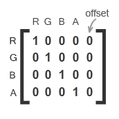
Above is an Identity matrix. This means, it will not affect the target as the values RR is 1, GG is 1 and so on. See matrices below for better understanding,
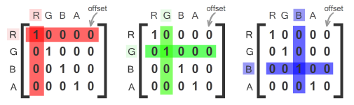
After observing the matrices above, it is clear that the first row and first column represents the red channel. Similarly, second row and second column represents green channel.
The blue channel lies in the third row and third column. Simple isn’t it.
And, the fourth row and fourth column represents alpha channel (i.e. transparency).
You can change values for all rows and columns within the range of (-255 to 255).
Below -255 or above 255 will not affect the target. It will have the same effect of -255 or 255.
In our example, we replaced 1 with 0.22 for RGB channels to reduce color amount from “myImage” instance. Thus, we had Grayscale effect.
It is time to know about the fifth column i.e. offset. What is the role of the fifth column?
It controls the amount of color in a selected row of a particular channel. Confused?
See the matrix below.
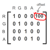
The above matrix will increase the red color amount of a target object.
If you want to remove red color from the image simply put -255 in place of 100.
In our script, replace the matrix array with the array shown below to remove red color from “myImage”. See below.
var matrix:Array = [ 1, 0, 0, 0, -255,
0, 1, 0, 0, 0,
0, 0, 1, 0, 0,
0, 0, 0, 1, 0 ];
I am sure that now, you are familiar with ColorMatrixFilter. Let us see how to apply this effect to bitmap data.
1) Create new Flash document for ActionScript 3.0.
2) Import a colourful image having enough amount red color.
3) Type the following code in ActionScript panel and test the movie.
var matrix:Array = [ 1,0,0,0,-255,
0,1,0,0,0,
0,0,1,0,0,
0,0,0,1,0 ];
var bmd:BitmapData = new BitmapData(stage.stageWidth, stage.stageHeight, false, 0xffffff);
bmd.draw(stage);
bmd.applyFilter(bmd, bmd.rect, new Point(), new ColorMatrixFilter(matrix));
var bmp:Bitmap = new Bitmap(bmd);
addChild(bmp);
A copy of stage object(s) with ColorMatrixFilter applied is on your screen.
Super Cool…. Now, let us move on to see another interesting filter ConvolutionFilter.
ConvolutionFilter
This filter also requires matrix transformation. The effects are generated affecting the neighbouring pixels of the current pixel to which this filter is processing. Thus, in this way every pixel is processed by this filter.
For best results, use 3 x 3 or 5 x 5 matrix. So, let us see an example. This example applies emboss effect to the target bitmap data.
1) Create new Flash document for ActionScript 3.0.
2) Import any image or draw some shapes on the stage.
3) Type the following code in ActionScript panel and test the movie.
var Emboss_Matrix:Array = [ -2, -1, 0,
-1, 1, 1,
0, 1, 2 ];
var bmd:BitmapData = new BitmapData(stage.stageWidth, stage.stageHeight, false, 0xffffff);
bmd.draw(stage);
bmd.applyFilter( bmd, bmd.rect, new Point(), new ConvolutionFilter( 3 , 3, Emboss_Matrix, 1 ) );
var bmp:Bitmap = new Bitmap(bmd);
addChild(bmp);
A copy of stage object(s) with ConvolutionFilter applied is on your screen.
To understand the working of Convolution Filter, we need to go through the following line used in the above code.
bmd.applyFilter( bmd, bmd.rect, new Point(), new ConvolutionFilter( 3, 3, Emboss_Matrix, 1 ) );
If you have already seen the sections BlurFilter and ColorMatrixFilter explained previously then you will be more familiar with the above line except the following part (Bold Words),
bmd.applyFilter(bmd, bmd.rect, new Point(), new ConvolutionFilter( 3, 3, Emboss_Matrix, 1 ));
This creates an instance of ConvolutionFilter with several argument passed to it.
For more information on ConvolutionFilter arguments see the link below,
Let’s go back to our line.
……….., new ConvolutionFilter( 3, 3, Emboss_Matrix, 1);
Let us simplify the piece above:
new ConvolutionFilter( arg1, arg2, arg3, arg4);
arg1 = Specifies the columns in the matrix. Match this value with your supplied matrix.
arg2 = Specifies the rows in the matrix. Match this value with your supplied matrix.
Since we are using 3 x 3 matrix, we put 3 for the two arguments above.
arg3 = This is the fundamental input since, it is a matrix which is responsible to produce end effect applied to the target. The following is the default matrix which will not affect the target:
var matrix:Array = [ 0, 0 ,0,
0, 1, 0,
0, 0, 0 ];
To visualize this matrix, think of 1 as a value for target pixel and rest are the values for neighbouring pixels at the top left corner, top, top right corner and so on. In this way, ConvolutionFilter goes through all pixels of targeted bitmap data. And finally, generates the result.
To get more clear view, try changing the values as shown below:
var matrix:Array = [ -0.2, 0 , 0,
0, 1, 0,
0, 0, -0.8 ];
Experiment it with yourself to be familiar with ConvolutionFilter.
arg4 = It is a divisor. It controls the intensity of the color of final result. Default is always 1. Since, you cannot divide by 0 then if you put 0 the 1 is used instead.
The following are the various matrices for various effects. Try using them in the above code.
Edge detection with divisor = 1:
|
1 |
0, -1, 0 |
|
1 |
-1, 4, -1 |
|
1 |
0, -1, 0; |
|
1 |
Sharpening with divisor = 1; |
|
1 |
0, -1, 0 |
|
1 |
-1, 5, -1 |
|
1 |
0, -1, 0 |
Blur with divisor = 5;
|
1 |
0, 1, 0 |
|
1 |
1, 1, 1 |
0, 1, 0
Huush…. we are about to reach the destination of our journey.
DisplacementMap Filter
This is yet another interesting filter which can be used to distort image. This filter when applied to bitmap data can create stunning effects. We are going to see one interesting example. In this example, we shall see how simple image of static water dramatically get converts into a live scene creating an illusion of water waves.
To achieve this effect, we shall take help of perlinNoise() method of BitmapData Class. Let us start.
1) Create new Flash document for ActionScript 3.0.
2) Copy the image shown below and paste into Flash stage.
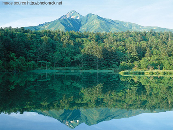
3) Set stage size equal to the above image. Align this image to stage centre.
4) We are going to” break apart” this image since we need to select the area acquired by water. So, while image is selected go to Modify > Break Apart or press CTRL + B(win) / CMD + B(mac).
5) Now, our image is Break Apart. So select bottom area (Acquired by water) as shown below.
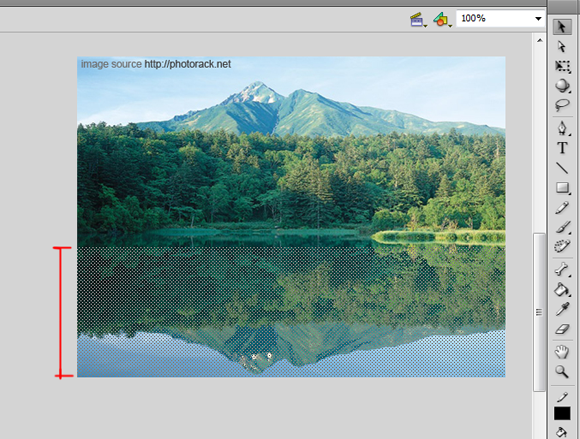
6) Do this step exactly as said.
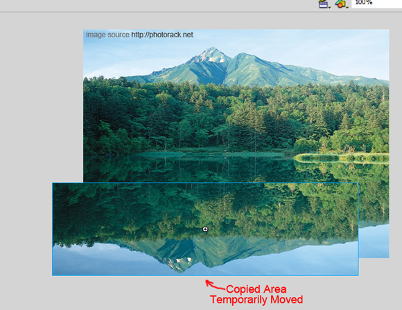
With the bottom area selected as shown above, copy it and press CTRL + SHIFT + V or go to Edit > Paste in Place and immediately press F8 or go to Modify > Convert to Symbol and convert it into movieclip.
We are doing this because it must be a copy of water area overlapped with an exact match with original image.
By the way, you can convert the selected area into movieclip without making a copy but the stage background color will mix up with the final result. It does not look real.
So, the best way is to keep the original image as it is and put a movieclip of a copy of water area above the original image. See the following image. The copied area movieclip is temporarily moved slightly for better understanding.
7) After converting into movieclip give instance name “waterWaves “.
Note: The steps 4 to 7 can be replaced by a technique discussed in Cropping Bitmap section. If we go by that way no need to break apart and movieclip conversion. Simply, draw a rectangle equal to water area and follow the steps of Cropping Bitmap section. I included steps 4 to 7 from beginner’s point of view.
8) Now, the real gist of this example. Yes ActionScript. Select the first and only key frame and press F9 to open ActionScript panel. Type the following code and test the movie.
//Bitmap data with stage width and height
var bmd:BitmapData = new BitmapData( waterWaves.width, waterWaves.height );
//Distort the water area to look like wave
var waveCreator:DisplacementMapFilter =
new DisplacementMapFilter( bmd, new Point( 0, 0 ),1, 2, 10, 60, “clamp” );
//Points for x and y values for perlin noise stored in array
var pt1:Point = new Point(0,0);
var pt2:Point = new Point(0,0);
var perlinOffset:Array = [pt1, pt2];
//Direction of water flow
var horizontalWaveDirection:Number = 0;
//Create wave animation with perlinNoise
function WaveAnimation( evt:Event ):void {
horizontalWaveDirection += 1;
perlinOffset[0].x = horizontalWaveDirection;
perlinOffset[1].y += 0.1;
bmd.perlinNoise ( 45, 6, 2, 50, true, false, 7, true, perlinOffset );
waterWaves.filters = [ waveCreator ];
}
addEventListener(Event.ENTER_FRAME, WaveAnimation);
I love Action Script….. A cool effect will be seen in few minutes.
Let us understand the code above.
First we shall put the sequence of tasks of the code as follows:
1) Create bitmap data w.r.t “waterWaves” movieclip.
var bmd:BitmapData = new BitmapData ( waterWaves.width, waterWaves.height );
2) Generate displacement map.
First of all, what is a displacement map? What does it do?
If you are 3D modeller or you know the 3D modelling then you are familiar with the displacement mapping. 3D displacement effects are different from 2D displacement mapping. In 3D, you also have a Z-Depth but in 2D you have to manage with x and y axis. Also, nowadays, 3D displacement mapping is highly improved.
In our case, how this displacement mapping works?
In order to displace the target image, a displacement mapping requires another image called as Texture Map. Based on this texture map the target image gets displaced. See the following image for better understanding.
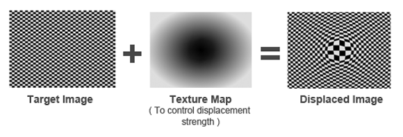
In our example, we are using the target image as water area (i.e. “waterWaves” movieclip) and Texture Map is generated by a powerful method perlinNoise(). This name was derived from its creator Ken Perlin. This method generates random noise which can be used to mimic the real world water waves by animating its parameters using AS3.
How to generate displacement mapping in AS3? You have to use DisplacementMapFilter() as shown below,
var waveCreator:DisplacementMapFilter =
new DisplacementMapFilter( bmd, new Point( 0, 0 ),1, 2, 15, 70, “clamp” );
We have provided 7 arguments to DisplacementMapFilter method.
arg1 = bmd. i.e. Bitmap Data (All pixels of “waterWaves” movieclip).
arg2 = new Point( 0, 0 ). i.e. starting point (upper left corner) of final image. This controls the x and y position. Since, we want to match the copied water area (i.e. “waterWaves” movieclip) with the original image, we put (0, 0) as starting point.
arg3 = 1. Represents the Color channel (1 stands for blue color channel) of target image for x-axis displacement.
arg4 = 2. This represents the Color channel (2 stands for green color channel) of the target image for y-axis displacement.
arg5 = 15. i.e. scaleX amount for displacement.
arg6 = 70 i.e. scaleY amount for displacement.
The above two argument’s (arg5 and arg6) values depends on source image.
arg7 = “clamp”. Specifies filter mode. There are 4 modes (“wrap”, “clamp”, “ignore”, ”color” ). We are using “clamp” because we want the displacement effect up o edges of the target image.
3) Array storing number of points those represents x and y offsets for each noise function generated by perlinNoise(). These offset values are the key factors for creating water flow. By constantly changing these values over a period of time generates various random noise functions.
Simplifying the above technique, Visualise it as an Animated Texture Map which we provided to DisplacementMapFilter() as last argument.
In our example, we are using two points those are sufficient to create flowing water. You can also use a single point. Still it will create water flow effect. But, we are using two points to have a precise control on water flow. We shall see it later. By the way, you can add more points as per requirement.
Let us see how we created and stored those two points in an array.
var pt1:Point = new point(0,0);
var pt2:Point = new point(0,0);
var perlinOffset:Array = [pt1, pt2];
These points are stored in an array which will play the role of last argument of perlinNoise() method.
4) Controlling direction of water flow,
var horizontalWaveDirection:Number = 0;
The above var keeps increasing over period of time in function “WaveAnimation()”.
Therefore, water flows from right to left. If you want to reverse the direction simply keep decreasing this value. For e.g. In our code, try replacing the line below in function “WaveAnimation()”,
horizontalWaveDirection += 1; //(increasing)
with,
horizontalWaveDirection -= 1; //(decreasing)
The flow of water is reversed. Simple isn’t it. You are the most powerful person in the world. You changed the direction of water in a matter of second.
5) Finally, the wave animation:
function WaveAnimation( evt:Event ):void {
horizontalWaveDirection += 1;
perlinOffset[0].x = horizontalWaveDirection;
perlinOffset[1].y += 0.1;
bmd.perlinNoise ( 45, 6, 2, 50, true, false, 7, true, perlinOffset );
waterWaves.filters = [ waveCreator ];
}
addEventListener(Event.ENTER_FRAME, WaveAnimation);
In the above function:
We first decided the direction of water flow we already saw in the above task.
horizontalWaveDirection += 1;
Then we applied increasing “horizontalWaveDirection” value to x offset of point one as:
perlinOffset[0].x = horizontalWaveDirection;
We also increased y offset value of point two as:
perlinOffset[1].y += 0.1;
Why increase x offset of point one by 1 and y offset of point two by 0.1?
Since, we want our water flow more horizontally i.e. along x-axis and less vertically i.e. along y-axis. Hence, x offset by 1 and y offset by 0.1.
If you use only one point, then it will be x and y offset for point one only.
Try commenting the above lines (perlinOffset[0].x and perlinOffset[1].y) in our code to turn off their effect and test the movie. Uncomment these lines back to turn them on when you are done.
You will see the wave effect but not the flowing water.
And now the important one – An animated texture map using perlinNoise() as,
bmd.perlinNoise ( 45, 6, 2, 50, true, false, 7, true, perlinOffset );
perlinNoise() method requires at least 6 arguments and we already specified 9 arguments.
arg1 = 45 i.e. baseX. It controls the frequency in x direction thus controlling the scale of a wave in x direction.
arg2 = 6 i.e. baseY. It controls the frequency in y direction thus controlling the scale of a wave in y direction.
arg3 = 2 i.e. numOctaves. This is an important parameter. Since, it controls the number of noise functions, those are used by perlinNoise() method to generate single noise (i.e. fractal sum of noise) . Take care while specifying this parameter. Though high values of numOctaves gives natural results but it also becomes CPU intensive. Hence, try to put nice number which will satisfy your need.
arg4 = 50 i.e. randomSeed. Every time you run this code it generates new kind of noise functions.
arg5 = true i.e. stitch. This creates the seamless texture.
arg6 = false i.e. fractalNoise. If fractal noise is set to false, it generates turbulence because turbulence is a part of fluid dynamics and further water is a part of fluid dynamics. So, use turbulence as it creates more realistic water waves than fractal noise.
arg7 = default 7. Combination of any of the four color channel values (BitmapDataChannel.RED, BitmapDataChannel.BLUE, BitmapDataChannel.GREEN, and BitmapDataChannel.ALPHA).
For more help visit the following link:
arg8 = true i.e. grayScale. For best result in displacement mapping gray scaled images are used. So, we need to create gray scale by setting value as true.
arg9 = perlinOffset i.e. array of points. We already discussed in tasks number 3 and 4. These points are animated to create water flow.
Finally, applying this filter as,
waterWaves.filters = [ waveCreator ];
And lastly, call to EnterFrame event for dynamic animation as,
addEventListener(Event.ENTER_FRAME, WaveAnimation);
The Final Destination…. For now, we have completed this part. More discussions are coming soon on bitmap data. That’s all. Have a TechnoArt month.
Conclusion:
In this topic we saw the working of BitmapData Class with the help of simple example. We also had an example on cropping an image.
We applied filters to bitmap data.
Two basic filters those are:
1) Blur Filter (Blured image example)
2) DisplacementMap Filter. (Water waves example)
And two special filters:
1) ColorMatrix Filter
2) Convolution Filter
Special filter because using these filters you can create more filters.
For example, using Convolution Filter you can create blurred as well as emboss effect. And using ColorMatrix Filter you can create gray scale effect as well as tint color effect.
[amember_protect guests_only]If you are already a Premium Member then just sign in and you can download the source files of this tutorial.
Not a member? Sign up today or read more about our Premium Member area.


[/amember_protect]


it was really excellent post! thanks a lot for sharing 🙂
Useful AS3 Flash tutorial, thanks for adding it
Instead of screaming “aaargh!” and pulling at my hair I’m going “whoa~” Very well done!! I’m not just taking apart your script and trying to see what it does, but your teaching it all right from the start. Wish I found this page first!
I’ve been able to simplify most of your filters by reusing the BitmapObject created in the ‘cropping’ lesson. Then simply adding the filter afterwards:
var effect_Blur:BlurFilter = new BlurFilter (16,16,3);
bmp.filters = [effect_Blur];
Exactly what I was looking for !!! Great work ! Thanx.
excellent tutorial, me helped to understand a little more the BitmapData class
thxs